Storm Drain
Storm Drain Lectures
Data and Resources
This lesson provides an introduction to the storm drain data used by FLO-2D.
Resources
FLO-2D Storm Drain Manual Storm drain Guidelines.
FLO-2D Plugin User Manual Storm Drain Editor.
EPA SWMM Documentation 5.0 is installed with EPA SWMM.
C:\Program Files (x86)\EPA SWMM 5.0\epaswmm5.chm
Open SWMM Documentation and Forum is an excellent resource for general storm drain modeling questions.
ChatGPT is an excellent quick reference but be careful because it often uses the wrong version of a software when it provides help.
Use the contact form if these resources do not provide a solution to a FLO-2D storm drain modeling problem.
Storm Drain Units
FLO-2D uses the following units for storm drain modeling.
Parameter |
Units (Imperial) |
Units (Metric) |
|---|---|---|
Discharge |
cubic feet per second (cfs) |
cubic meters per second (cms) |
Volume |
cubic feet (ft³) |
cubic meters (m³) |
Depth |
feet (ft) |
meters (m) |
Area |
square feet (ft²) |
square meters (m²) |
Elevation |
feet (ft) |
meters (m) |
Velocity |
feet per second (ft/s) |
meters per second (m/s) |
Time |
hours (hr) |
hours (hr) |
Date |
MM/DD/YYYY |
MM/DD/YYYY |
Time Series |
HH:MM |
HH:MM |
Storm Drain Feature Overview
Point features (nodes): inlets, junctions, manholes, outfalls, storage units
Polyline features (links): conduits, pumps, orifices
Node Overview - Inlet, Junction
This lesson explains how to review and interpret inlet and junction shapefile data for storm drain modeling in FLO-2D. Inlet and junction nodes contain attributes that define how they interact with the grid and storm drain network.
Documentation
Use the Storm Drain Guidelines (Chapter 2) to understand inlet types:
Type 0: Junction (no interaction with surface)
Type 1: Curb opening
Type 2: Curb with gutter
Type 3: Grate
Type 4: Unique (e.g. headwall)
Type 5: Manhole
Node Overview - Outfall, Storage Unit
This lesson explains how to review and configure outfalls and storage units in storm drain shapefiles.
Link Overview - Conduits
This lesson explains how to review and configure conduits in storm drain shapefiles.
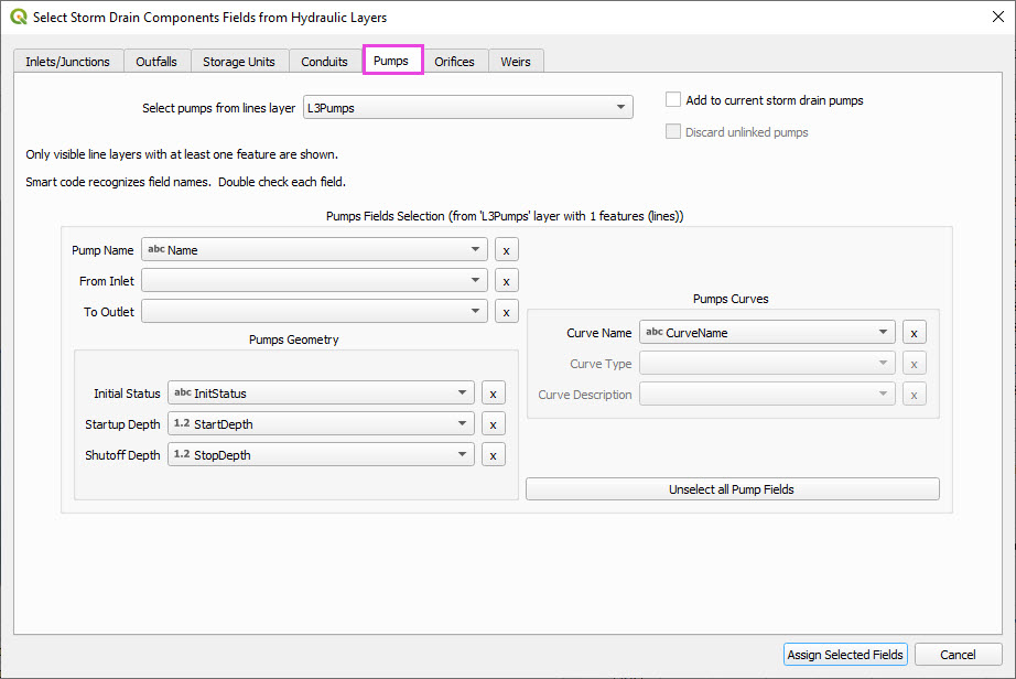
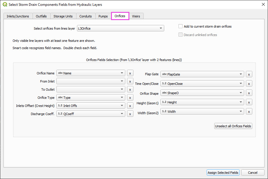
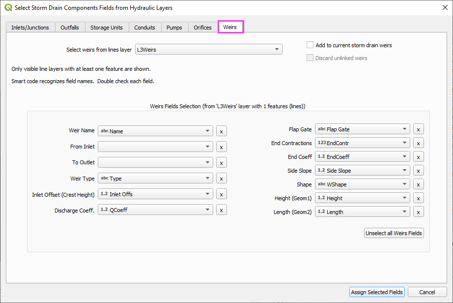
Link Overview - Pump, Orifice, Weir
This lesson explains how to review and configure pumps, orifices, and weirs in storm drain shapefiles.
Simple Storm Drain Tutorial
Create a Storm Drain from Shapefiles
This simple lesson shows how to create a simple storm drain from Shapefiles.
Note
It will be easier to view these videos on YouTube.
Set the video playback speed to 2x to complete the lessons faster.
The videos are more detailed whereas the text gives the minimum steps needed to complete the project.
This lesson walks through building a simple storm drain system from shapefiles.
Step 1: Load Shapefiles
Open the Simple Storm Drain Layers folder.
Drag and drop the appropriate shapefiles into QGIS.
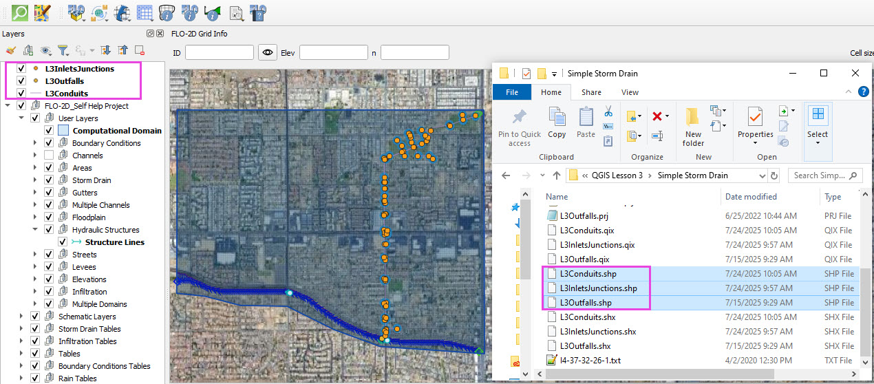
Save the project and when prompted to save the layers to the GeoPackage, select No.
These layers can be removed when no longer needed.
These features will be copied to the Storm Drain User Layers and are no longer needed when that process is complete and the test run is successful.
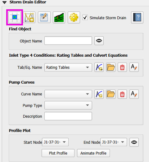
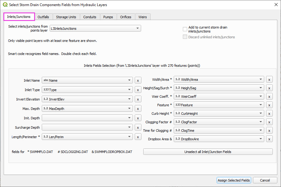
Step 2: Assign Shapefile Fields
Open the Storm Drain Editor and click Select Components from Shapefile.
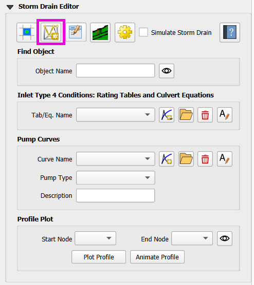
Point layers like inlets and outfalls will show up in the dropdown.
Assign each required field from the shapefile attributes:
Example: Inlet Name → name, Type → type, etc.
Turn off unused or null-value fields to avoid unnecessary entries.
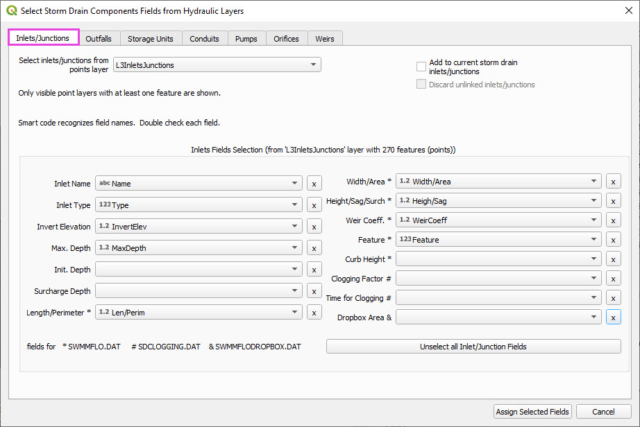
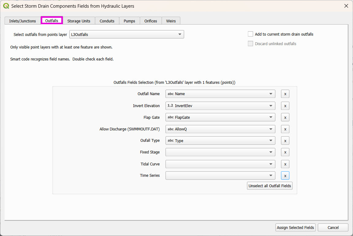
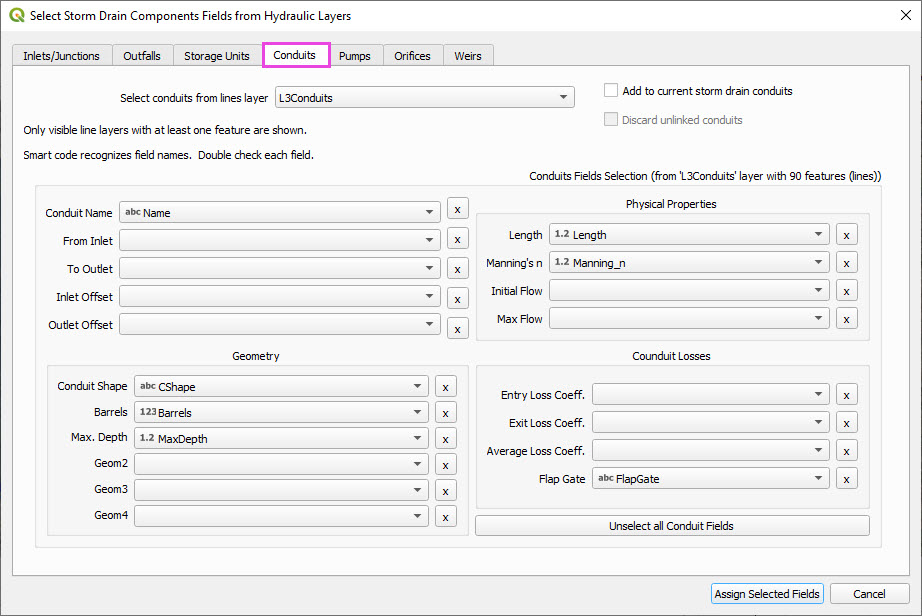
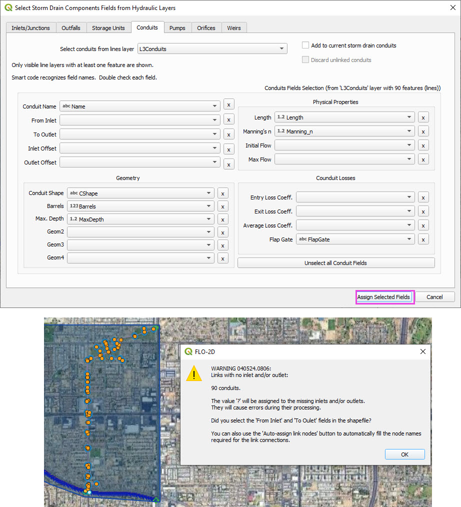
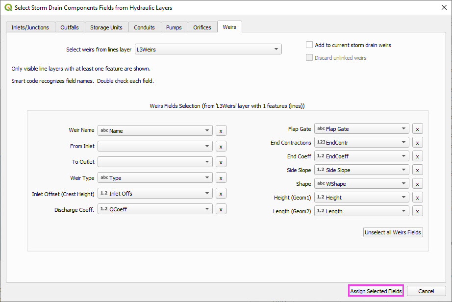
Click Assign Selected Fields, then click OK for the warning that follows.
Step 3: Assign Nodes to Links
Click the Auto-Assign Links and Nodes button.
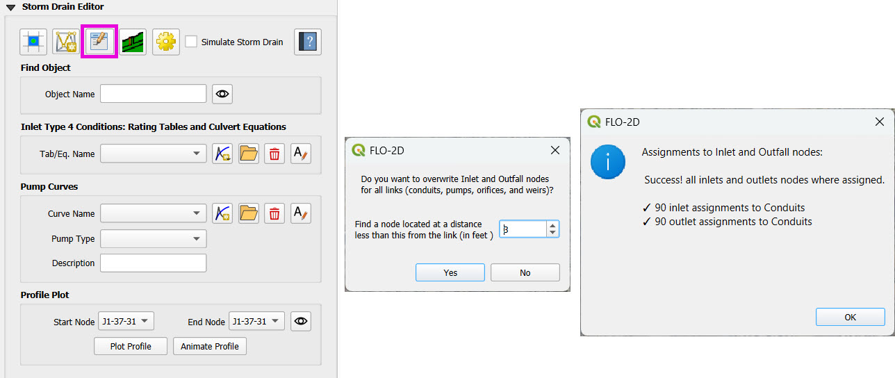
This assigns start and end nodes to each conduit.
Uses the closest node within a 3-ft radius from the first and last vertex of a conduit.
Warning
Make sure conduit directions are correct using the Reverse Line Tool in the Advanced Digitizing Toolbar.
Use the Snapping Tool to ensure precise vertex-node connections.
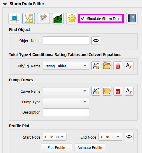
Check the Simulate Storm Drain box to turn it on.
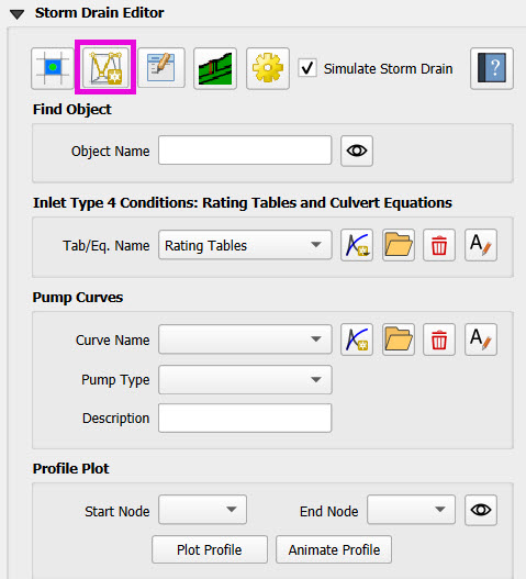
Step 4: Add Type 4 Rating Tables and Culverts
Go to the Type 4 Table Editor.
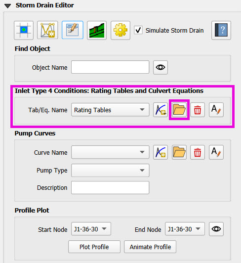
Import rating tables for one type 4 inlet.
File names must match inlet names (e.g.,
41.txtfor inlet 41).Format for rating tables: Depth on the left, Discharge on the right.
Step 5: Set Storm Drain Control Parameters
Set the start and end time of the simulation (e.g., 10 hours).
Ensure it matches any time series used.
Adjust the report step, flow units (CFS/CMS), and routing method.
Leave advanced defaults unless needed.
Step 6: Schematize and Run
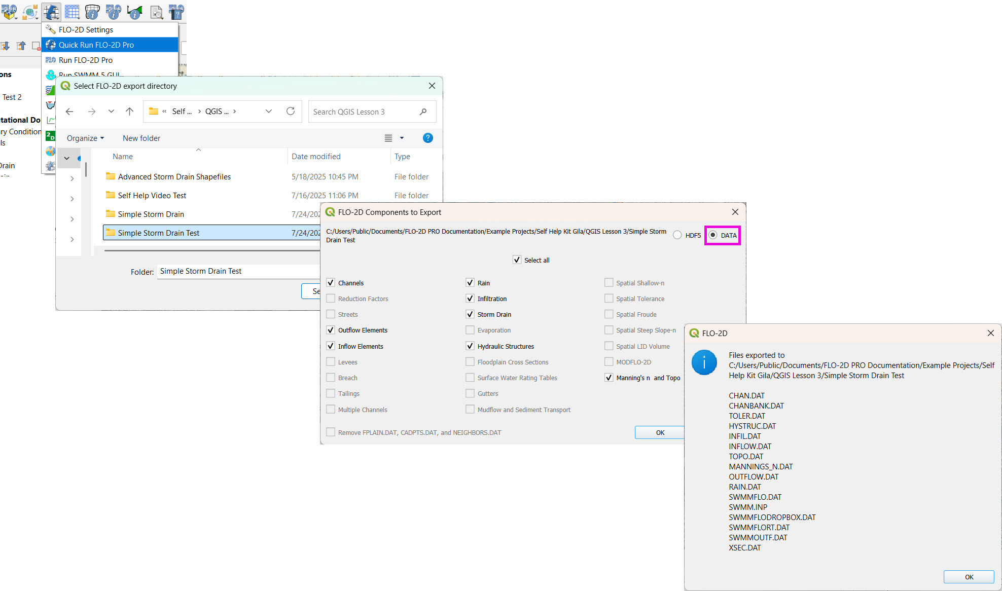
Click Schematize Storm Drain to export
SWMM.OUTF,SWMM.FLOW,DROPBOX.DAT, etc.
Click Quick Run to simulate.
Output files will populate the designated folder.
Tip
If errors occur, check the shapefile connections, field assignments, or go to a FLO-2D Troubleshooting video in the series.
Advanced Storm Drain Tutorial
This advanced lesson shows how to create a storm drain from Shapefiles. It uses more complex shapefiles and features than the simple storm drain lesson.
Note
It will be easier to view these videos on YouTube.
Set the video playback speed to 2x to complete the lessons faster.
The videos are more detailed whereas the text gives the minimum steps needed to complete the project.
Storm drain checklist.
Here is a checklist of tasks that need to be completed to successfully build the advanced storm drain model.
[ ] Inspect shapefile fields carefully. A single incorrect field assignment can cause the storm drain to fail or run incorrectly.
[ ] Auto-assign nodes.
[ ] Adjust outfall locations so all outfalls are placed on a left bank node.
[ ] Check channel outfall elevations and ensure they are at or slightly higher than the channel invert elevation.
[ ] Ensure conduit length is a minimum of 30 ft, which is the cell size.
[ ] Add Type 4 rating tables and culverts to the Type 4 inlets.
[ ] Add a pump table and assign it to P1.
[ ] Create a storage unit volume table and assign Storage1 to all storage units.
[ ] Add the Grover Street junction external inflow data.
[ ] Check storm drain control settings.
[ ] Schematize the network.
[ ] Perform a test run.
Create a Storm Drain from Shapefiles - Advanced
This lesson walks through building an entire storm drain system from shapefiles, defining rating tables, storage units, and pump curves, and then running the simulation.
Step 1: Load Shapefiles
Open the Advanced Storm Drain Layers folder.
Drag and drop the appropriate shapefiles into QGIS.
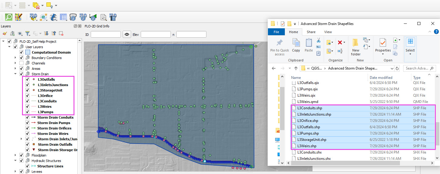
Save the project and when prompted to save the layers to the GeoPackage, select No.
These layers can be removed when no longer needed.
These features will be copied to the Storm Drain User Layers and are no longer needed when that process is complete and the test run is successful.
Step 2: Assign Shapefile Fields
Open the Storm Drain Editor and click Select Components from Shapefile.
Point layers like inlets, outfalls, and storage units will show up in the dropdown.
Assign each required field from the shapefile attributes: - Example: Inlet Name → name, Type → type, etc.
Turn off unused or null-value fields to avoid unnecessary entries.
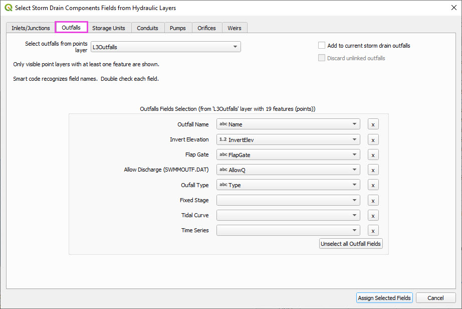
Click Assign Selected Fields, then click OK for the warning that follows.
Warning
Warning 1 The yellow warning bar is normal with respect to the advanced storm drain system. It has 1 junctions and 4 outfalls that are positioned outside of the grid area. This is done intentionally to demonstrate that it is OK to have these feature outside of the grid area so long as they do not need to connect to the surface. Those outfalls should be set to Sink or 0 in the Allow Discharge field. The junctions should have a name that doesn’t start with “I” because they do not interact with the surface.
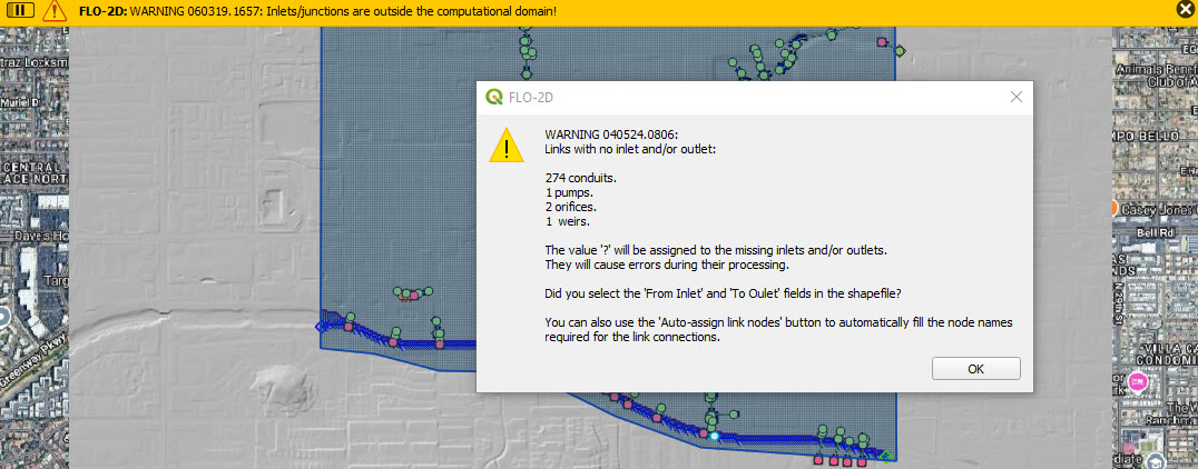
Warning 2 The Warning dialog box is also normal because the node names were not filled during the field assignment step. The fields will be filled in the next step.
Step 3: Auto-Assign Nodes to Links
Click the Auto-Assign Links and Nodes button.
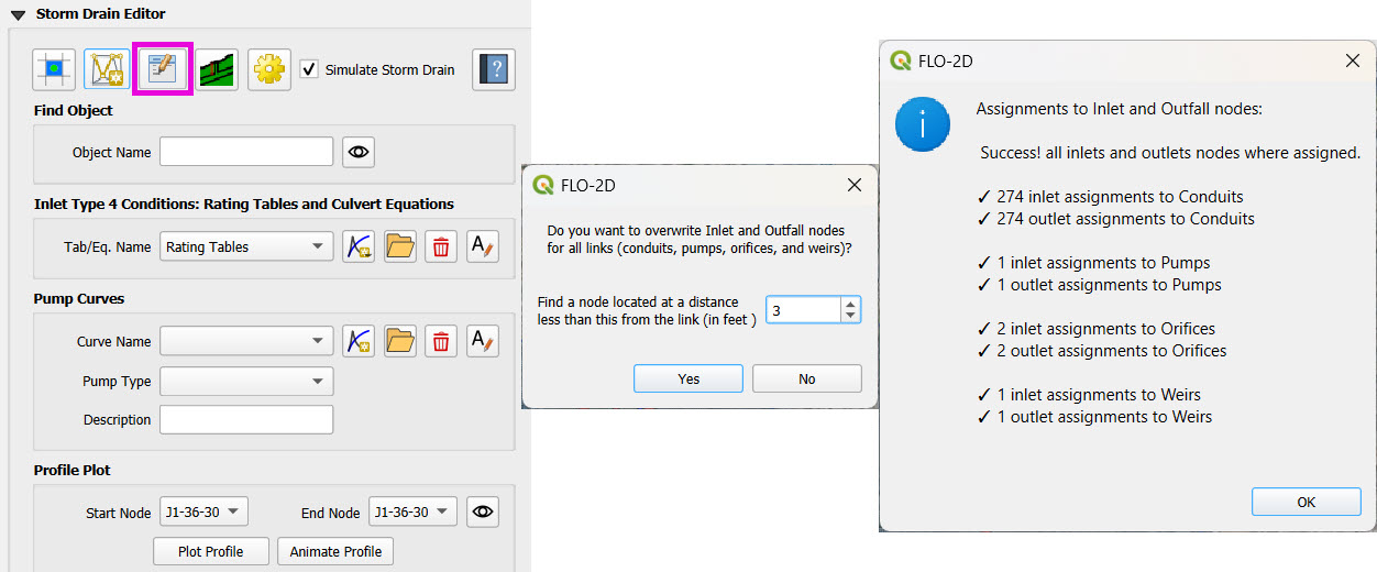
This assigns start and end nodes to each conduit.
Uses the closest node within a 3-ft radius from the first and last vertex of a conduit.
Warning
Make sure conduit directions are correct using the Reverse Line Tool in the Advanced Digitizing Toolbar.
Use the Snapping Tool to ensure precise vertex-node connections.
Check the Simulate Storm Drain box to turn it on.

Step 4: Check Outfalls
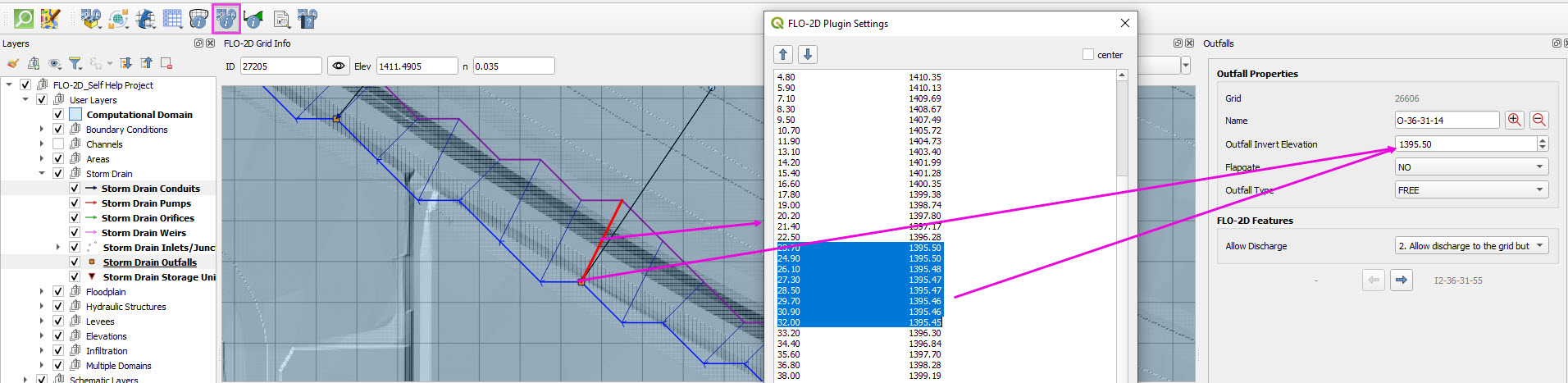
Ensure every outfall that is near the channel is aligned to a left bank grid.
Move outfalls and conduit vertices as needed to ensure they are contained by a left bank grid element.
Select the outfall and conduit layers and click the Edit Pencil.
Use the Snapping Tool to ensure precise vertex-node connections.
Click the vertex to pick it up. Move the cursor to the left bank grid and click again to drop it.
Outfalls should have the same an elevation that is the same or slightly higher than the channel cross section.
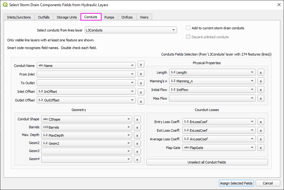
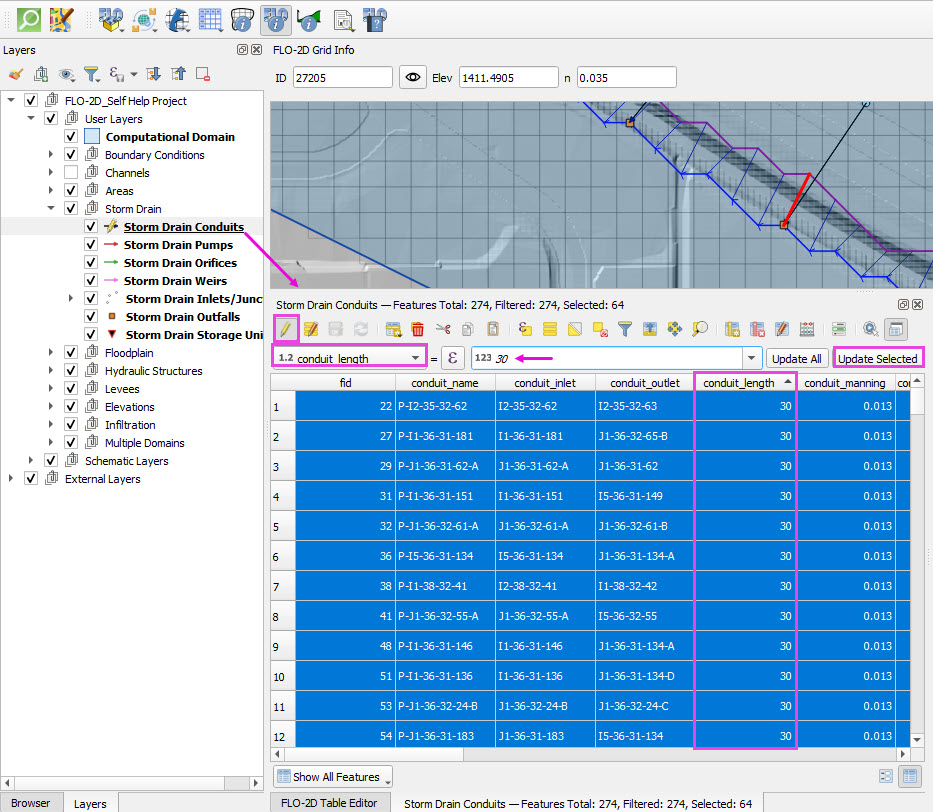
Step 5: Check Conduit Length
Open the Conduits attribute table.
Sort the table by the length field.
Select the conduits than are less than 30 ft long.
Set the field editor to the length field.
Set the length of the conduits to 30 ft.
Apply 30 ft to the selected conduits.
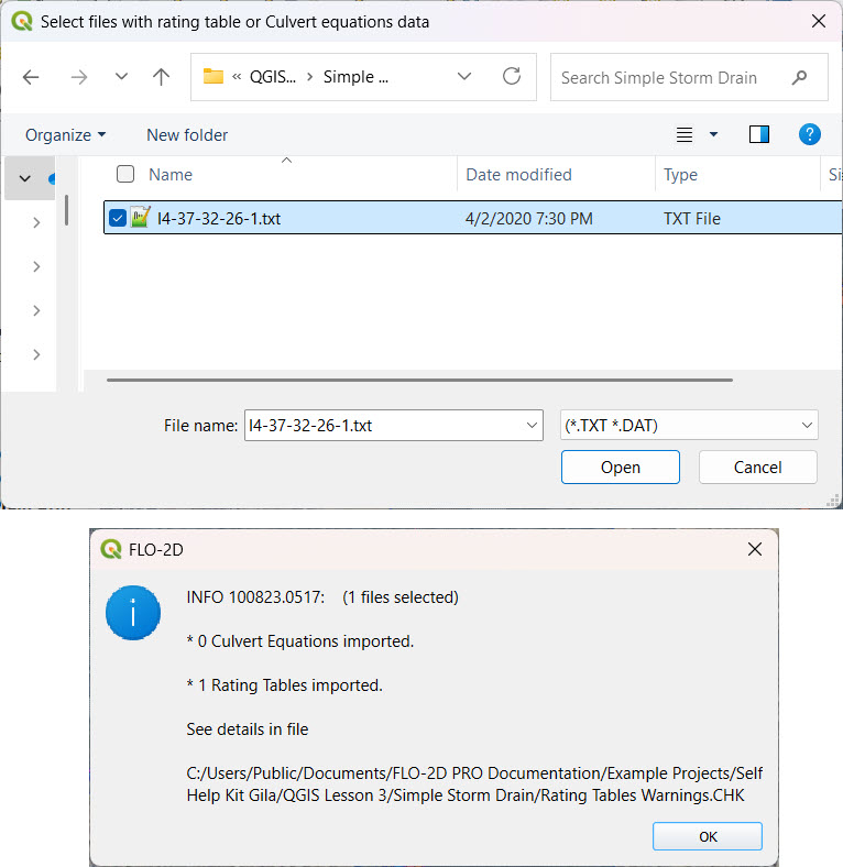
Step 6: Add Type 4 Rating Tables and Culverts
Go to the Type 4 Table Editor.

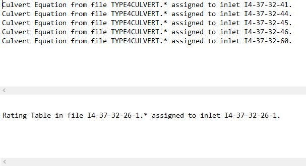
Import rating tables or culvert equations for each type 4 inlet.
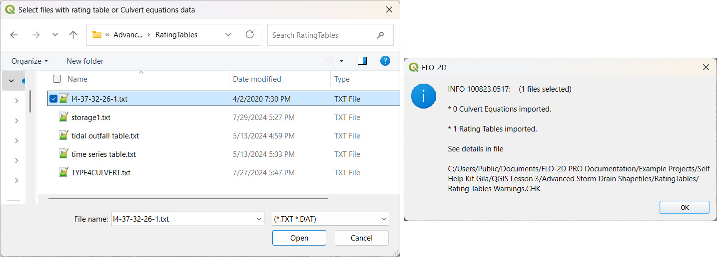
The rating table file names must match inlet names (e.g.,
I4-47-32-26-1.txtmatches inletI4-47-32-26-1).Format for rating tables: Depth on the left, Discharge on the right.
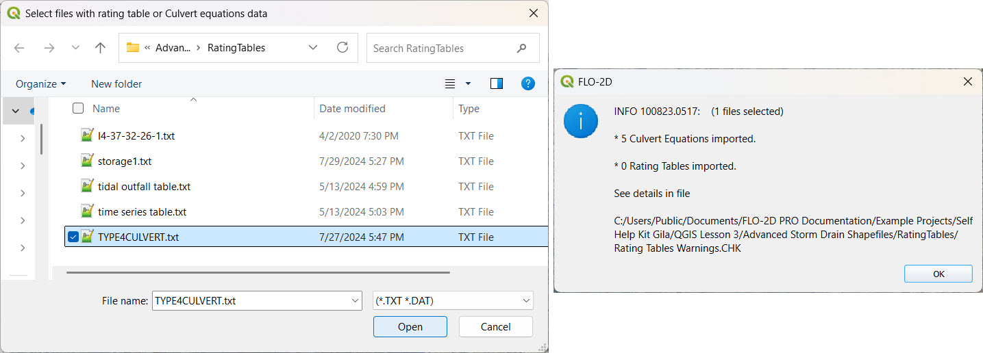
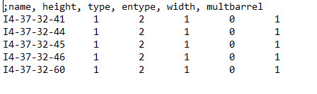
The culvert equations are set for type 4 inlets.
The culvert data needs to be written to a file names TYPE4CULVERT.txt.
The format of the file is important.
After the import is complete, review the warning text file to check for any issues.
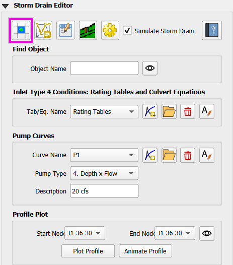
Step 7: Add Pump Curve Data
Add a pump curve via the Pump Table interface.
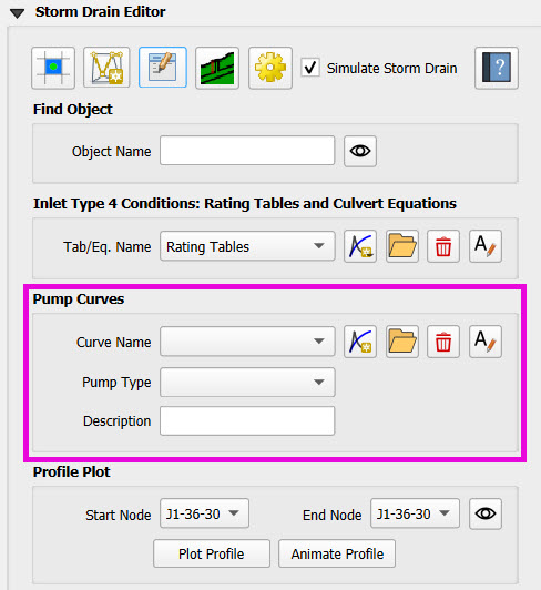
Name it to match the pump (e.g.,
P1).
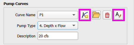
Enter a depth-discharge pair (e.g.,
1,10,2,20).
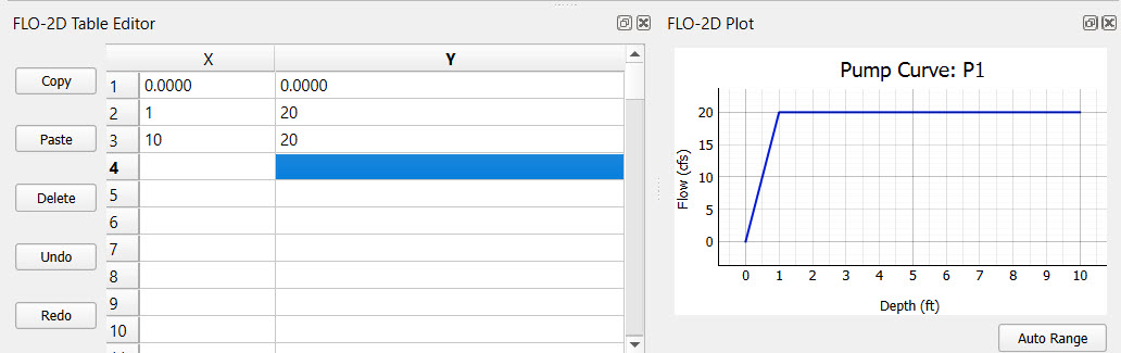
Data is saved automatically when the table is modified.
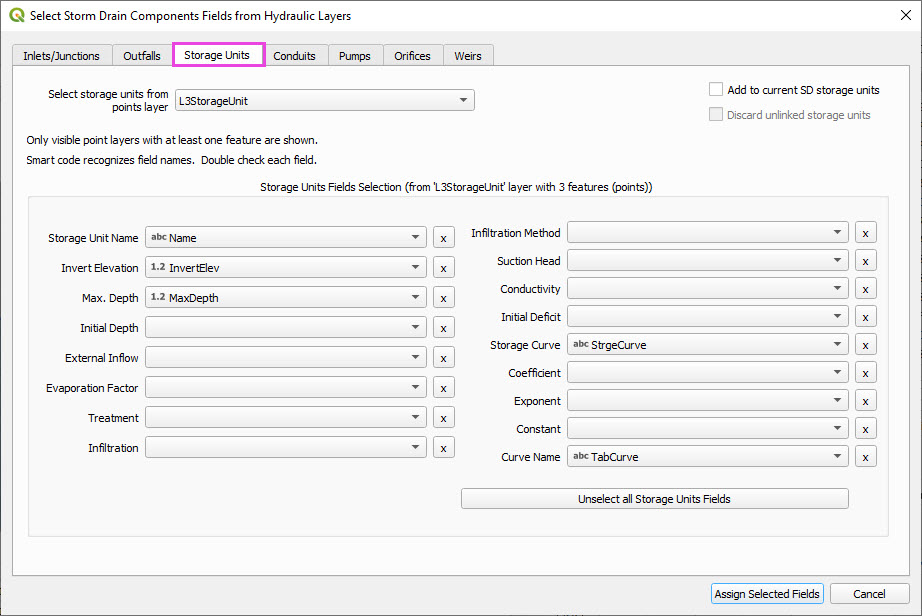
Step 8: Add Storage Unit Curves
Open Storage Units attribute table.
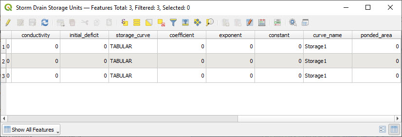
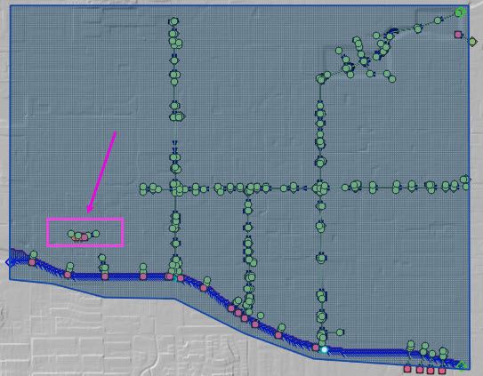
Zoom to the storage units.
Use the FLO-2D Info Tool to open the storage curve editor.
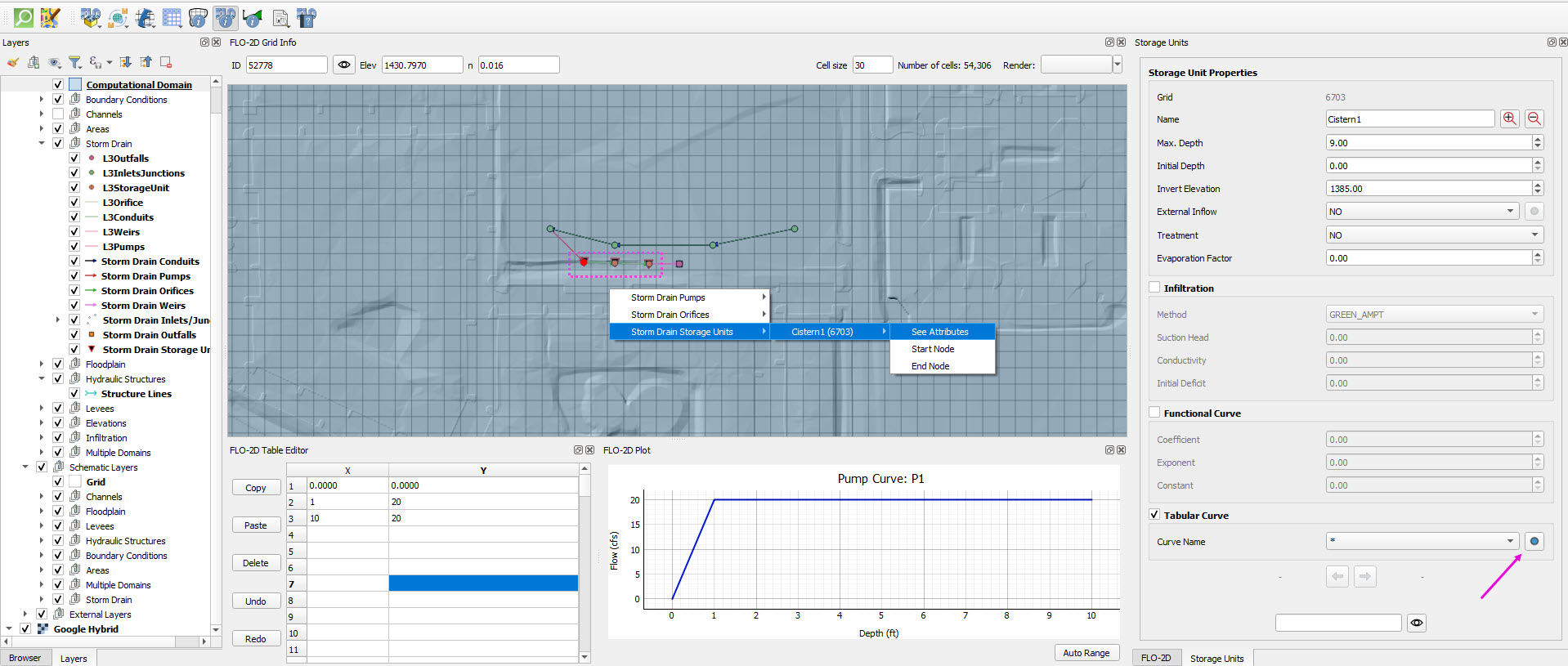
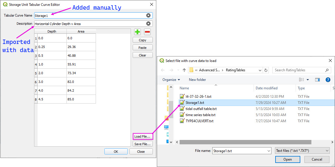
Import a tab-delimited text file or paste Excel values.
Repeat the select feature process for the other two storage units.
They should already be set because they had the correct curve name in the attribute table field.
All three storage units will use the same storage curve named Storage1.
Step 9: Set External Inflow for Grover Street Junction
Zoom to the northeast corner of the storm drain system.
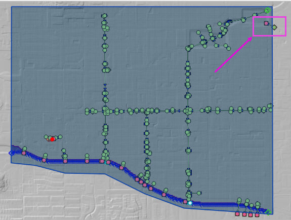
Use the FLO-2D Info Tool to open the junction editor of the junction that is outside the grid area.
Set the Grover Street junction to have an external inflow = Yes.
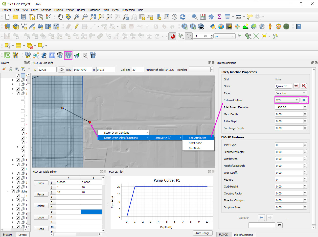
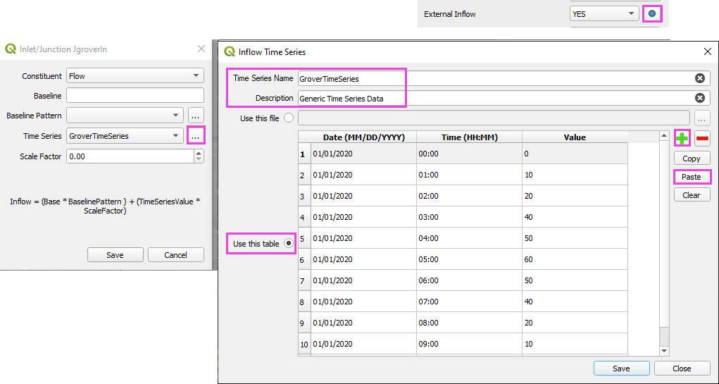
Click the Blue button to open the time series editor.
Click the three dots next to Time Series to open the time series editor.
Assign the Time Series Name and Description as shown in the image below.
Add one blank line to the table.
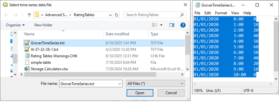
Copy the time series data from the GroverTimeSeries.txt file.
Paste the data into the time series table.
Close both editors.
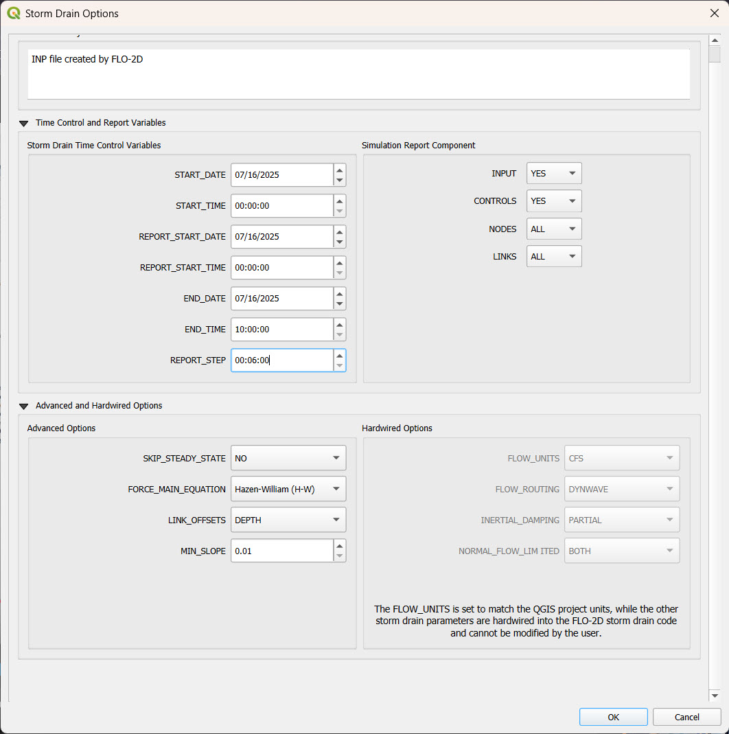
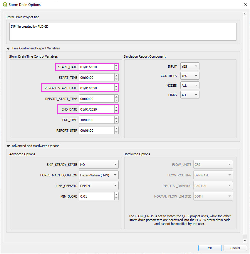
Step 10: Set Storm Drain Control Parameters
Set the start and end time of the simulation (e.g., 10 hours).
Ensure the start time and end time matches any time series data used. (Grover Street Time Series)
Check the report step, flow units (CFS/CMS), and routing method.
The Hardwired parameters are not editable in this dialog. If they are modified in the swmm.inp file, they will be ignored by the FLO-2D Storm Drain engine.
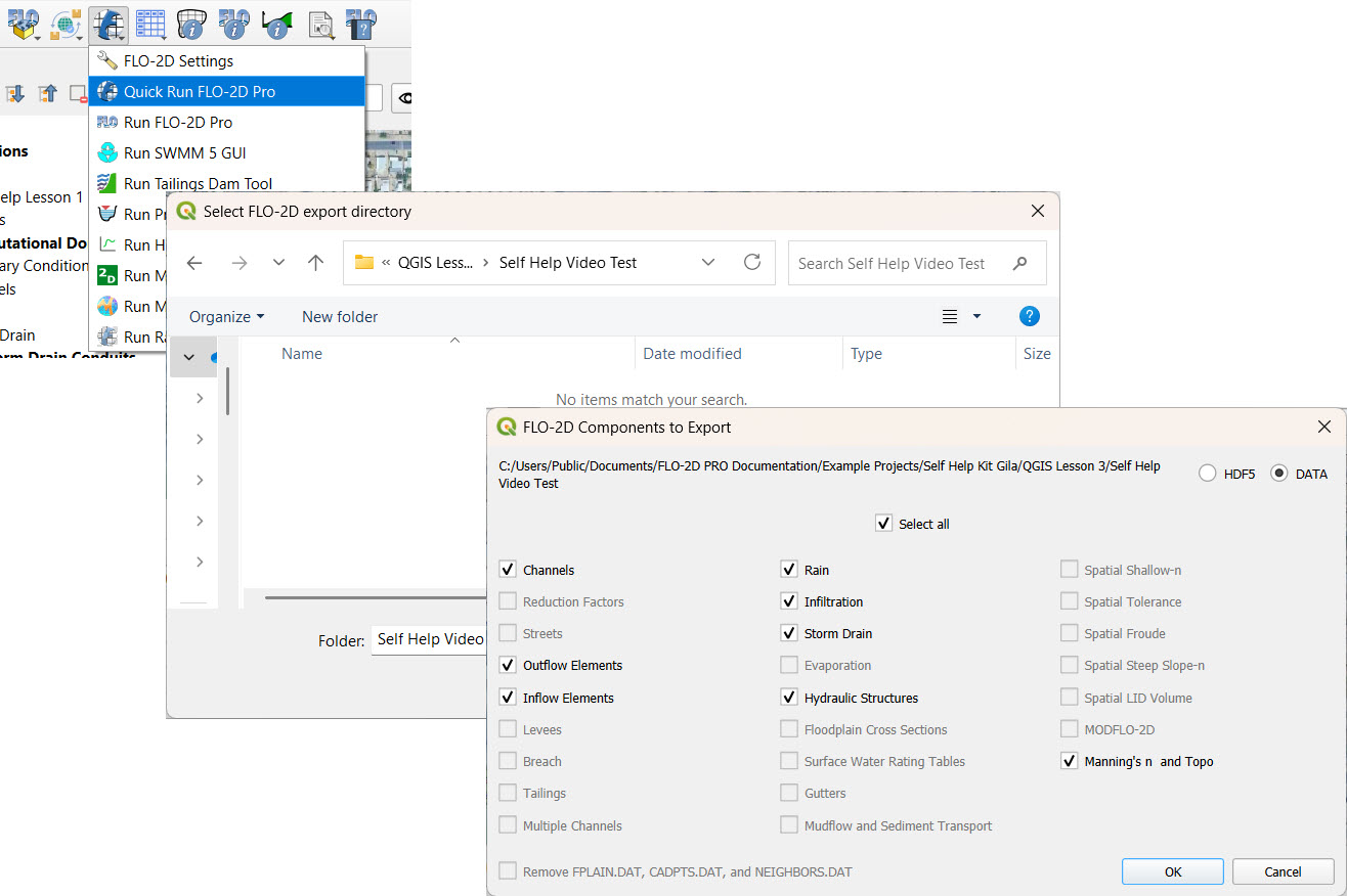
Step 11: Schematize and Run
Click Schematize Storm Drain to export
SWMM.OUTF,SWMM.FLOW,DROPBOX.DAT, etc.
Click Quick Run to simulate.
Output files will populate the designated folder.

Tip
If errors occur, check the shapefile connections, field assignments, or go to a FLO-2D Troubleshooting video in the series.
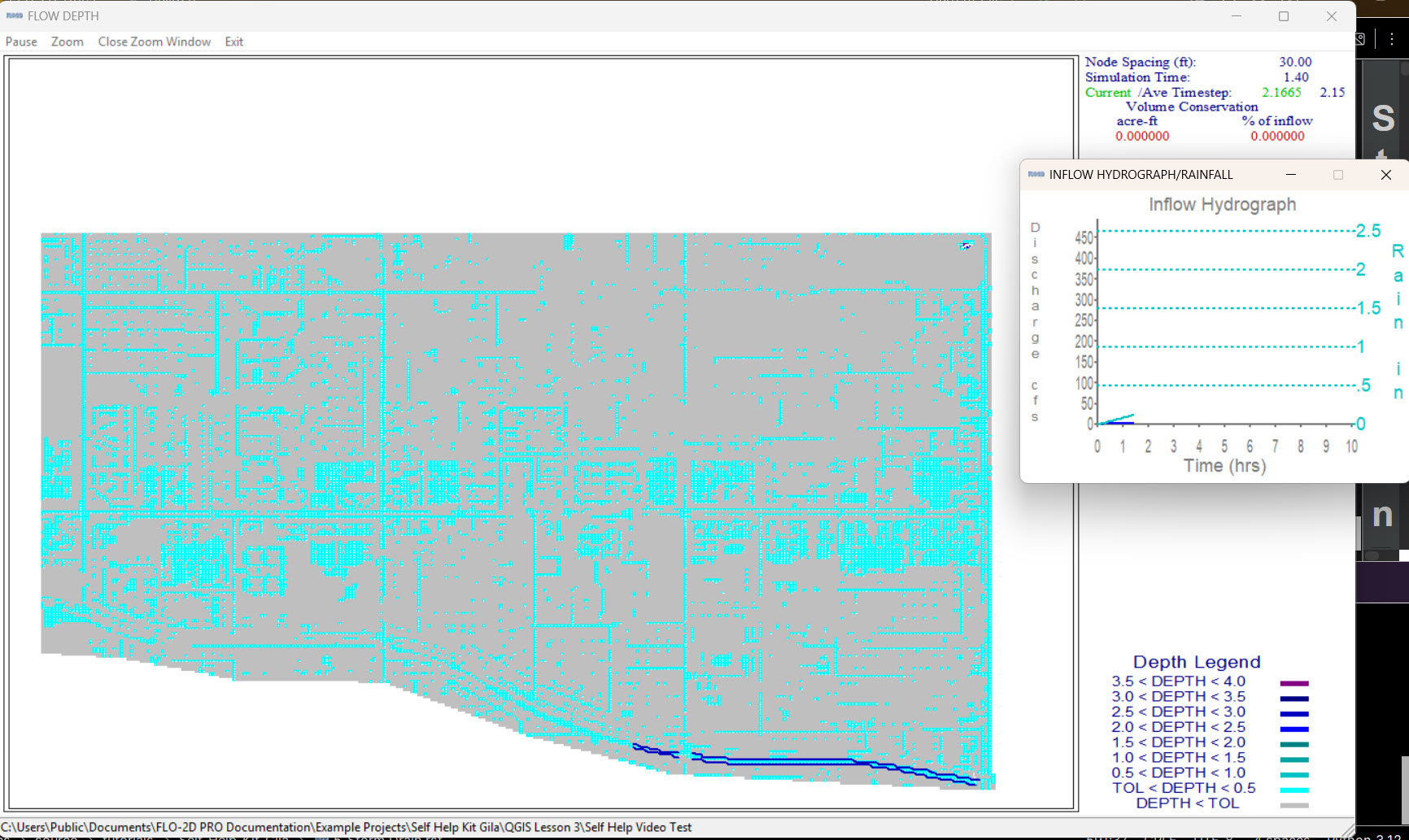
Summary and Review Results
This lesson shows the process to review results and confirm that a storm drain model is set up and working correctly.
Storm Drain from SWMM.INP
Under Construction…